Dielectric strength testing assesses the ability of electrical devices, insulation materials, and insulation structures to withstand high voltages. Its primary objective is to check whether insulation can withstand operating voltages or overvoltages without compromising its performance, ensuring that the insulation performance of equipment meets safety standards.
Basic Principles of Dielectric Strength Testing:
The basic principle of dielectric strength testing is to apply a voltage higher than the normal operating voltage to the insulation of the device under test and maintain it for a specified time. If the insulation performs well during this period, the applied voltage will only produce minimal leakage current.
Specific Steps Include:
• Applying High Voltage: Apply a voltage higher than the normal operating voltage to the insulation of the device under test. Typically, the test voltage is twice the operating voltage of the device plus 1000V. For example, for a device with an operating voltage of 220V, the test voltage would be 2*220V + 1000V = 1440V.
• Measuring Leakage Current: Measure the leakage current passing through the insulation within a specified time (usually not less than 5 seconds). If the leakage current remains within the specified range, the insulation performance of the device is considered satisfactory.
• Voltage Ramp-Up and Stabilization: According to the IEC 61010 standard, the test voltage must gradually rise to the required test voltage value (e.g., 5kV) within 5 seconds. Maintain the test voltage stable on the tested insulation for at least 5 seconds.
• Evaluating Insulation Performance: Compare the measured leakage current value with the leakage current threshold specified by the standard to determine whether the insulation performance of the device under test meets the requirements.
• Voltage Ramp-Down: After the test is completed, the test voltage must gradually decrease to zero within the specified time to ensure the safety of the testing equipment and personnel.
Testing Standards and Specifications:
The technical specifications and measurement standards for dielectric strength testing vary depending on the tested product. Generally, the basic provisions for dielectric strength testing include:
• Leakage Current Between Live Parts and the Enclosure: Dielectric strength testing typically measures the leakage current between live parts and the enclosure.
• Test Voltage: The test voltage is set at twice the operating voltage of the device under test plus 1000V.
• Test Duration: The test voltage should gradually rise and remain applied for not less than 5 seconds.
• Leakage Current Threshold: The measured leakage current value should be compared with the leakage current threshold specified by the standard to determine whether the insulation performance is acceptable.
The test voltage for some products may be higher than the specified values above, and specific requirements should be referenced from relevant technical standards and product specifications.
Duration of Dielectric Strength Tester Testing:
The duration of dielectric strength testing varies depending on the standards and specifications of the product. Generally, dielectric strength testing requires a duration of 60 seconds, which is strictly enforced in safety compliance testing organizations and factory laboratories. However, on production lines, long-duration testing is often challenging to implement due to the emphasis on production speed and efficiency. Therefore, in actual production, shortened testing times and increased test voltages are commonly employed to meet requirements.
Common Testing Durations Include:
• 60-Second Test: Dielectric strength testing typically requires a duration of 60 seconds in safety compliance testing organizations and laboratories to ensure comprehensive testing of equipment insulation.
Testing Durations on Production Lines:
• Shortened Testing Times: On production lines, many organizations allow for achieving the same testing objectives by shortening testing times and increasing test voltages to improve efficiency.
• 1-Second Test: Some newer safety standards, such as Appendix A of IEC60335-1 and IEC60950-1, explicitly state that routine testing times can be as short as 1 second. Such short-duration testing is more common in actual production.
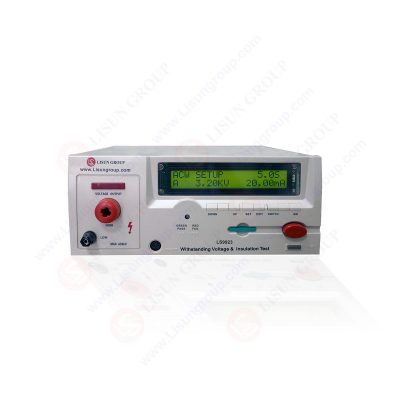
LS9923 Programmable Withstanding Voltage & Insulation Test
Structure and Components of Dielectric Strength Tester:
The dielectric strength tester mainly consists of three major parts: the voltage boosting section, the control section, and the display circuit. Below are detailed descriptions of each part:
Voltage Boosting Section:
• The voltage boosting section comprises a voltage regulator transformer, a boosting transformer, and switches for connecting and disconnecting the voltage boosting section power.
• Voltage Regulator Transformer: Regulates the 220V input voltage to provide power to the boosting transformer.
• Boosting Transformer: Boosts the output voltage through the voltage regulated by the voltage regulator transformer to generate the high voltage required for testing.
• Power Switch: Controls the connection and disconnection of the power to the voltage boosting section to manage the voltage boosting operation.
• Users can control the output voltage of the boosting transformer by adjusting the voltage regulator transformer to achieve the desired test voltage.
Control Section:
• The control section manages current sampling, time control, and alarm functions.
• Current Sampling: Monitors the leakage current of the device under test, providing feedback signals when the leakage current exceeds the set value.
• Timer Circuit: Sets and controls the duration of the test, usually including a countdown function.
• Alarm Circuit: Triggers audio and visual alarms when the leakage current exceeds the set value and disconnects the voltage boosting circuit power.
• Start and Reset Control: Powers on the voltage boosting section upon receiving the start signal and powers off the voltage boosting circuit power after the test is completed or upon receiving the reset signal.
• The control section ensures precise control of current and time during testing and provides safety protection when necessary.
Display Circuit:
• The display circuit is used to real-time display test parameters, including voltage, current, and time.
• Voltage Display: Displays the output voltage value of the boosting transformer for user monitoring of the test voltage.
• Current Display: Displays the current value monitored by the current sampling section to assist in determining insulation performance.
• Time Display: Displays the countdown time of the timer circuit to ensure that the test duration meets standard requirements.
• The display circuit provides users with real-time test data to ensure operational transparency and accuracy.
Conclusion:
The dielectric strength tester achieves high-voltage testing of the device under test through the coordinated operation of the voltage boosting section, control section, and display circuit. The voltage boosting section provides the required test voltage, the control section ensures the safety and accuracy of the testing process, and the display circuit provides real-time feedback of test parameters. Through reasonable design and operation, the dielectric strength tester effectively detects the insulation performance of equipment, ensuring its safety under normal operating conditions.
https://www.lisungroup.com/news/technology-news/precision-operation-of-dielectric-strength-testeing-ensuring-electrical-product-safety-and-reliability.html
.jpg)


Comments
Post a Comment