Introduction:
In the field of electromagnetic compatibility (EMC), common mode interference is a significant concern, making common mode inductors one of the essential components we frequently utilize. This article aims to provide a brief overview of the principles and applications of common mode inductors.
Understanding Common Mode Inductors:
Common mode Inductors, also known as common mode interference suppressors, are devices with a ferrite core used to mitigate common mode interference. They consist of two coils of the same size and number of turns wound symmetrically on the same ferrite toroidal core, forming a four-terminal device. Common mode inductors exhibit significant inductance for common mode signals, playing a crucial role in suppressing such interference while having minimal impact on differential mode signals. Their operation is based on the phenomenon where the magnetic flux in the core adds up when a common mode current flows, resulting in significant inductance and impedance for common mode currents. Conversely, when a differential mode current flows, the magnetic flux cancels out, resulting in minimal inductance, allowing the differential mode signal to pass through without attenuation. Thus, common mode chokes effectively suppress common mode interference signals in balanced circuits without significantly affecting the transmission of normal differential mode signals.
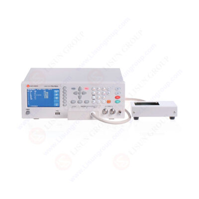
LS8517CX Common Mode Inductor Balance Tester
Fabrication Requirements of Common Mode Inductors:
Insulation of Conductors: Insulation between the conductors during winding is necessary to prevent short circuits under transient overvoltages.
• Core Saturation: The core should not saturate when the coil carries transient large currents to maintain the normal operation of the common mode choke.
• Insulation Between Core and Coils: Insulation between the core and coils is essential to prevent breakdown under transient overvoltages.
• Single-Layer Winding: Coils should be wound as single-layer as possible to reduce parasitic capacitance and enhance the ability to withstand transient overvoltages.
Considerations in Common Mode Inductors Selection:
In selecting common mode inductors, it is crucial to consider both the desired filtering frequency range and the common mode impedance. Typically, a higher common mode impedance is preferred. Therefore, appropriate common mode inductors should be chosen based on the impedance frequency curve provided in the device datasheet. Additionally, attention should be paid to the influence of the common mode choke on the differential mode impedance, particularly in high-speed ports.
Conclusion:
As electronic devices, computers, and household appliances become increasingly prevalent, electromagnetic noise interference has become a significant concern, akin to a public hazard. In response, electromagnetic interference (EMI) filters have emerged as a new type of composite device widely utilized to suppress grid noise effectively and enhance the anti-interference capabilities of electronic equipment and system reliability. EMI filters find extensive applications in electronic measurement instruments, computer room equipment, switching power supplies, measurement and control systems, and other fields.
https://www.lisungroup.com/news/company-news/exploring-the-essence-of-common-mode-inductors-and-addressing-common-mode-interference-issues-in-manufacturing-processes.html
.jpg)
.jpg)

Comments
Post a Comment