Probe Test
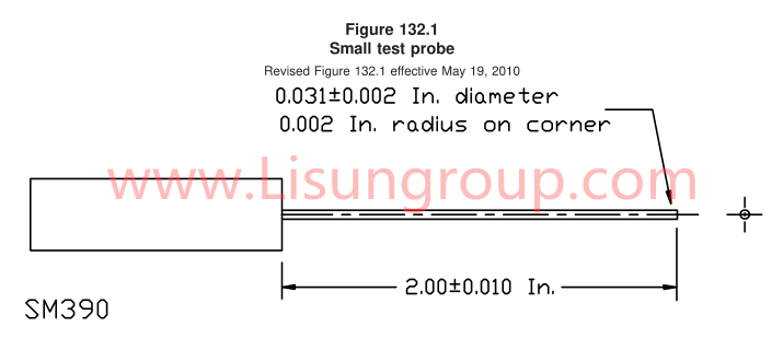
A tamper-resistant receptacle shall not permit contact to be made between the probe test shown in Figure 132.1 and Figure 132.2 and any live part of the receptacle through the outlet slots when tested as described in this section.
Twelve previously untested devices are to be used for this test. The probe test shown in Figure 132.1 is to be applied to each of the outlet slot openings of the receptacle with a force of 8 ounces (2.2N) in an attempt to bypass the tamper-resistance mechanism. A suitable indicating device (such as an ohmmeter, battery-and-buzzer combination, or the like) is to be connected between the probe and the wiring terminal of the outlet slot being tested to determine whether contact is made.
Small Probe Test of UL498 Figure 132.1
The probe test is to be manipulated in the outlet slots in any orientation that may permit access to live parts within the receptacle.
Twelve devices previously tested in 132.2 are to be used for this test. The probe test shown in Figure 132.2 is to be applied to each of the outlet slot openings of the receptacle with a force of 10 pounds (45N) in an attempt to bypass the tamper-resistance mechanism. A suitable indicating device (such as an ohmmeter, battery-and-buzzer combination, or the like) is to be connected between the probe and the wiring terminal of the outlet slot being tested to determine whether contact is made.
The probe test is to be inserted in the outlet slots successively in three directions in any orientation that may permit access to live parts within the receptacle. The probe is applied for approximately 5 seconds in each of the three directions. During each application the gauge shall not be moved or rotated and shall be withdrawn when moving from one direction to the next.
https://www.lisungroup.com/news/technology-news/small-probe-test-of-ul498-figure-132-1.html
.jpg)
.jpg)

Comments
Post a Comment